Establishing Elena's foundation
Elena received her name and the initial responsibilities of her three major subsystems were defined. A dual-battery power architecture was also selected to isolate motor noise from the controllers and display.
Title and date
Establishing Elena's foundation — August 30, 2026
Development stage
Architecture and power-system planning.
Goal
Define Elena's major subsystems and develop a stable power arrangement for the motor controller, two microcontrollers, sensors, and E-Ink display.
Components used
- Mother PC application
- Raspberry Pi Pico 2 W — Nolena
- Waveshare RP2040-Plus — Melissa
- Yahboom four-channel encoder motor controller
- Two separate 2S 18650 battery packs
- GS2678 DC-DC buck converter
- Waveshare E-Ink display
- Qwiic/I²C sensors
What changed
The complete robot was named Elena. The project was divided into three cooperating systems:
- Mother handles the desktop interface, logs, TCP commands, and Ollama.
- Nolena controls movement, sensors, IR, and Wi-Fi.
- Melissa controls the E-Ink display and communicates with Nolena over UART.
Separate batteries were chosen for motors and electronics.
Wiring or schematic
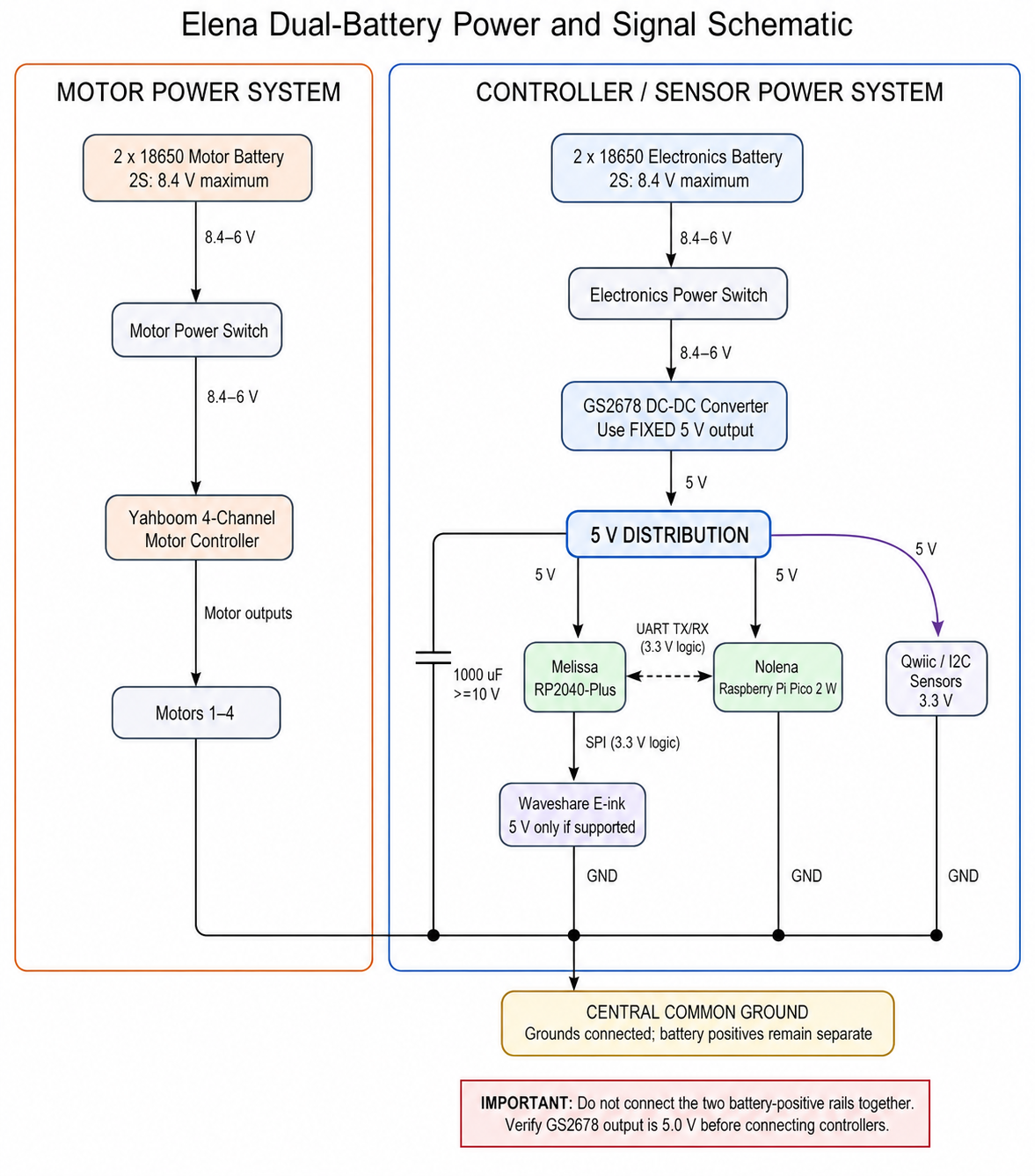
The GS2678 provides the shared regulated 5 V controller rail. Both Nolena and Melissa receive power from this rail.
The current hardware does not use separate 2S BMS/charging modules or inline fuses. The schematic reflects the direct, switched battery connections used in the build.
The motor and electronics battery-positive rails remain separate. Their grounds are connected to provide a shared reference for I²C, UART, and other control signals.
Software changes
No firmware change was required for this planning milestone. The future software architecture will preserve the responsibilities assigned to Mother, Nolena, and Melissa.
Test results
The proposed electronics supply converts the second 2S battery's 8.4–6 V range to a regulated 5 V supply for the controllers and supported peripherals.
Problems encountered
Motor startup and stall currents can create voltage dips and electrical noise capable of resetting wireless microcontrollers or disrupting the display.
Solution
Use separate 2S battery packs for motor power and electronics power, with a common ground for communication. Regulate the electronics battery through the GS2678 and add local bulk capacitance.
Photographs/video
Photographs and test video will be added after the first assembled power-system test.
Next steps
- Assemble and fuse both battery branches.
- Set and verify the GS2678 fixed output at 5.0 V.
- Test Nolena and Melissa under simultaneous Wi-Fi and E-Ink activity.
- Test motor startup while monitoring both supply rails.
- Record voltage, current, temperature, and reset behavior.